A dry bulk tank truck is a specialized vehicle designed for transporting dry materials with particle diameters no greater than 0.1 mm, such as cement, fly ash, and mineral particles. It is mainly used in industries such as manufacturing, agriculture, construction, and power plants. The reason for its widespread use lies in the following advantages:
- Reduced labor consumption and improved production efficiency;
- Significant savings in packaging materials, which reduces transportation costs;
- Minimal material loss, typically with a loss rate of less than 0.5%;
- Guaranteed material quality, as the transported materials are less prone to moisture or spoilage;
- Reduced dust and lower environmental pollution.
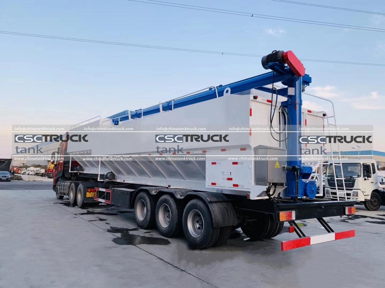
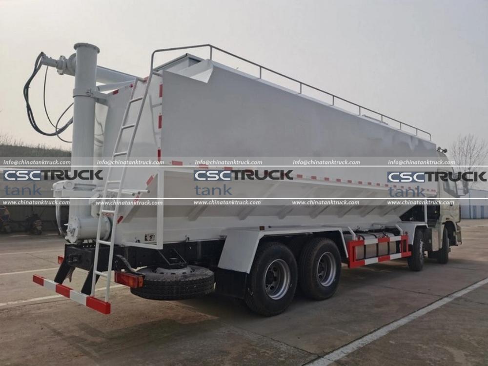
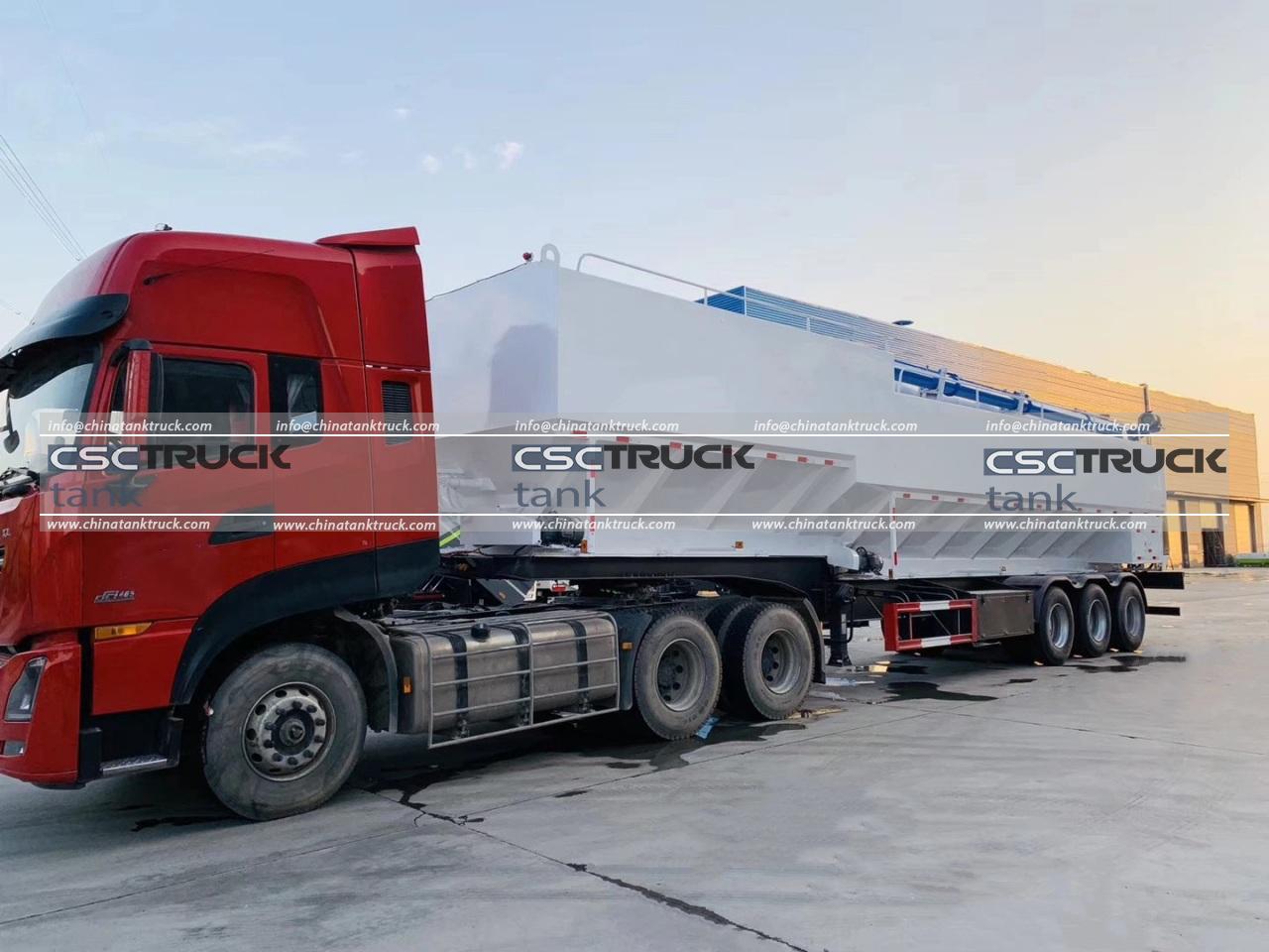
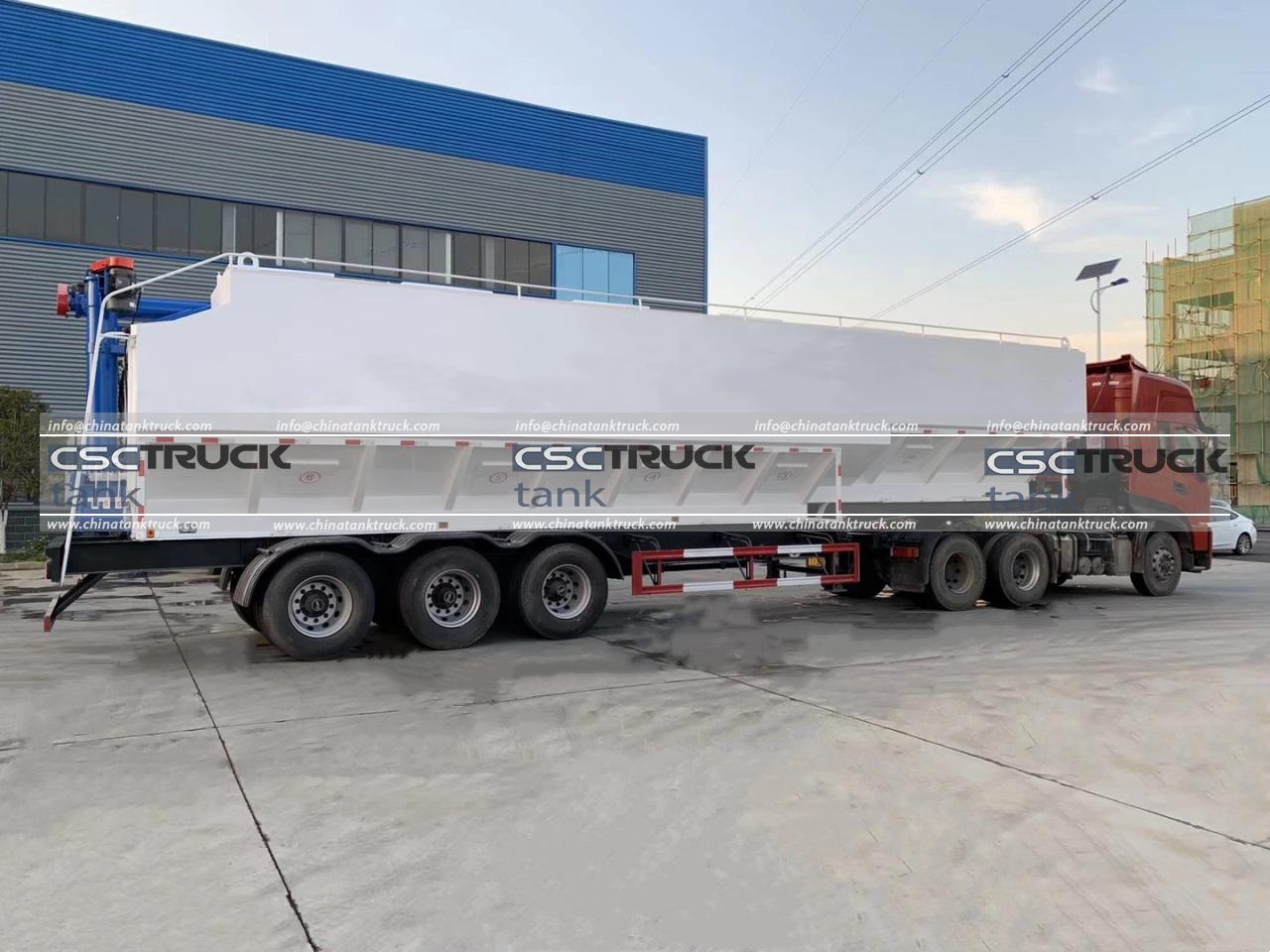
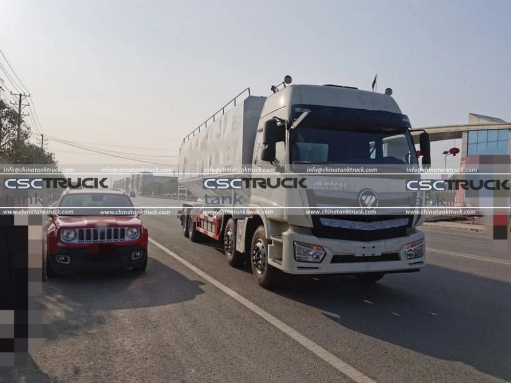
Structure of the Dry Bulk Tank Truck
The truck is composed of 2 main parts: the chassis and the upper assembly. The upper assembly includes the transmission system, tank, pipeline system, and auxiliary devices.
Working Principle
The engine power is transmitted to the air compressor through a power take-off (PTO) device. The compressor generates compressed air, which enters the tank and passes through a fluidization device, turning the material into a fluid-like state. A pressure difference forms inside and outside the tank, causing the material to be discharged through the unloading system to a designated location.
What is Material Fluidization?
When gas enters a powder layer from the bottom of the container and the gas flow rate exceeds a certain threshold, the friction between the gas and the material equals the weight of the powder particles. At this point, the particles are no longer supported by the fluidized bed and begin to flow freely from higher to lower levels, with the surface remaining level—similar to the behavior of liquids. If there’s an opening in the side of the container, the powder can even be expelled from it. This phenomenon is known as material fluidization.
Transmission System
The transmission system primarily includes the PTO, drive shaft, and air compressor. On the outside of the tank is an electromagnetic tachometer that monitors the compressor’s speed. The engine throttle can be adjusted via a throttle controller, which in turn changes the compressor’s rotational speed.

Pipeline System
After being output by the compressor, air passes through a check valve and a ball valve to enter each compartment. The secondary air assist pipeline connects to the unloading pipeline and provides supplementary air to aid material discharge. A pressure relief valve is installed on the top of the tank to release residual pressure inside the tank—used mainly before opening the manhole cover or when stopping unloading midway.
Unloading Pipeline
This system consists of a material suction port, a butterfly valve, a discharge steel pipe, a discharge pipe joint, and a discharge hose. A pressure-resistant vibration pressure gauge is mounted on top of the tank to monitor internal pressure changes and guide the unloading process.